Diverter Spare Parts
|
|
|
How to Replace a Diverter Piston Valve AssemblyPrint Page // Jump to Diagram // Jump to Parts |
|
| This instruction process is written for cast diverter sets but the process is very similar for the 3 piece telephone diverter sets. |
|
| 1) | Turn off the hot and cold water supply to the diverter set. |
| 2) | For a cast diverter set like the RU9481, remove the diverter set by undoing the 2 x 20mm union nuts at the back and lifting the set off. For a 3 piece diverter body like the SA8458 unscrew the diverter from the 1/2" BSP male wall thread after removing the telephone cradle. |
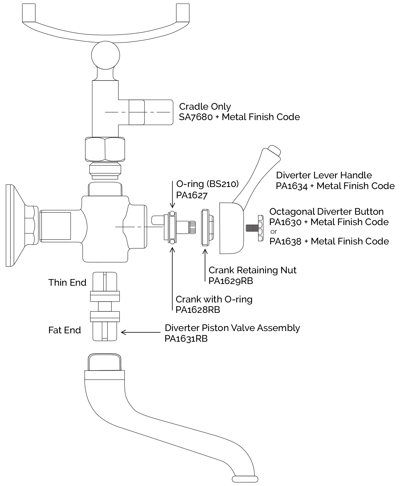
| 3) | Unscrew the octagonal indicator button on the centre lever. |
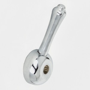
| 4) | Remove the lever handle. |
| 5) | Remove the brass crank retaining nut using an adjustable wrench on the 2 flats and unscrewing it out of the diverter body. |
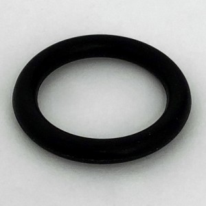
| 6) | Pull out the diverter crank with o-ring. We suggest the o-ring to be replaced if being removed. |
| 7) | The diverter piston can only be taken out via the outlet which has been Loctited in place. The best way to break the Loctite seal is to immerse the diverter set in hot water for 3 to 4 minutes. Then giving the duckbill outlet a sharp tap with a rubber mallet.
The duckbill outlet unscrews in a clockwise direction (this direction is based on standing over the duckbill with the nose of the duckbill pointed to the ground, if you turn the diverter upside down with the outlet pointed up, the direction to unscrew is anti-clockwise). |
| 8) | With the outlet removed the diverter piston will fall out the bottom. |
| 9) | The new piston has a small square at one end and a larger square at the other end. The small square goes into the diverter body first and when the piston is pushed in all the way then the duckbill outlet can be re-screwed back on using Loctite No. 569 on the thread to seal the outlet in place. The outlet must be screwed all the way up or the diverter will not function correctly. |
| 10) | It is suggested that the diverter body and all parts be cleaned and lubricated with plumbers grease. |
| 11) | Proceed with installation of the crank with o-ring, crank retaining nut, handle, and button. Screwing the set back in a reverse procedure. Please note that the Octagonal Handle Retaining Button only needs to be lightly tightened as it is only there to prevent the external handle coming off the crank spline. It does not hold in any of the diverter internals. |
| 12) | Turn the water back on and check for leaks. Check that the diverter lever works ok. |
 Loading, please wait...
-
![Photo: PA1628RB - Diverter Crank with O-Ring [Raw Brass]](https://www.cbideal.com.au/n/media/catalog/product/cache/1/small_image/300x/9df78eab33525d08d6e5fb8d27136e95/p/a/pa1628rb_diverter_crank_with_o-ring_-_raw_brass_-_thumbnail.jpg)

-
-
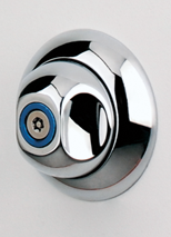
![Photo: PA1629RB - Diverter Crank Retaining Nut [Raw Brass]](https://www.cbideal.com.au/n/media/catalog/product/cache/1/small_image/300x/9df78eab33525d08d6e5fb8d27136e95/p/a/pa1629rb_diverter_crank_retaining_nut_-_raw_brass_-_thumbnail.jpg)
-
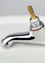
![Photo: PA1631RB - Diverter Piston Valve Assembly [Raw Brass]](https://www.cbideal.com.au/n/media/catalog/product/cache/1/small_image/300x/9df78eab33525d08d6e5fb8d27136e95/p/a/pa1631_thumbnail.jpg)
-
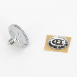
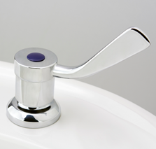
SKU: PA1630Diverter Octagonal Handle Retaining Button with Legacy Indicator
 Ex GST:
$29.99
Inc GST:
$32.99
Ex GST:
$29.99
Inc GST:
$32.99
-
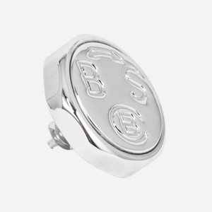
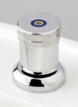
SKU: PA1638Diverter Octagonal Handle Retaining Button with Engraved Indicator
Ex GST:
$38.76
Inc GST:
$42.64
-
-
-
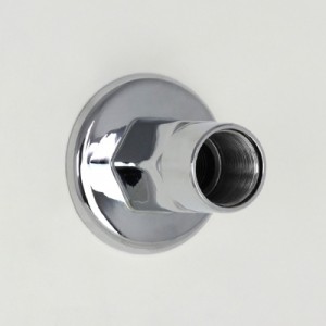
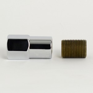
SKU: SA8451Short Flanged Extension Only for 3 Piece Diverter Outlet (8458 Sets)
Ex GST:
$109.20
Inc GST:
$120.12
-
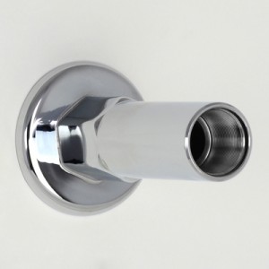
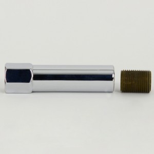
SKU: SA8452Medium Flanged Extension Only for 3 Piece Diverter Outlet (8458 Sets)
Ex GST:
$131.02
Inc GST:
$144.12
-
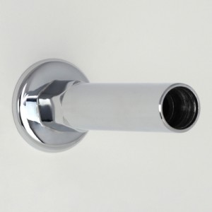
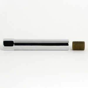
SKU: SA8453Long Flanged Extension Only for 3 Piece Diverter Outlet (8458 Sets)
Ex GST:
$152.89
Inc GST:
$168.18
-
-
-
-
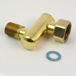
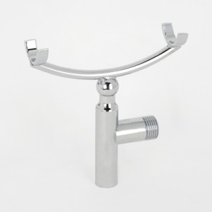
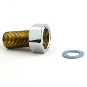
SKU: SA7931Diverter Wobble Joint (1/2" BSP Male to 3/4" BSP Female Union)
Ex GST:
$193.60
Inc GST:
$212.96
-

SKU: SA7933Diverter Wobble Joint (1/2" BSP Female to 3/4" BSP Female Union)
Ex GST:
$213.78
Inc GST:
$235.16
-
-
-
-
-